Transformers
Transformers are modeled as in [T1].
Dyn11
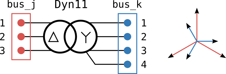
"transformers":[
 {"bus_j": "Bus_0",  "bus_k": "Bus_1",  "S_n_kVA": 1000.0, "U_j_kV":20, "U_k_kV":0.42,
  "R_cc_pu": 0.01, "X_cc_pu":0.04, "connection": "Dyn11",   "conductors_j": 3, "conductors_k": 4},
                ],
Dyn1
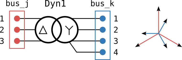
"transformers":[
 {"bus_j": "Bus_0",  "bus_k": "Bus_1",  "S_n_kVA": 1000.0, "U_j_kV":20, "U_k_kV":0.42,
  "R_cc_pu": 0.01, "X_cc_pu":0.04, "connection": "Dyn1",   "conductors_j": 3, "conductors_k": 4},
                ],
Ygd11_3w
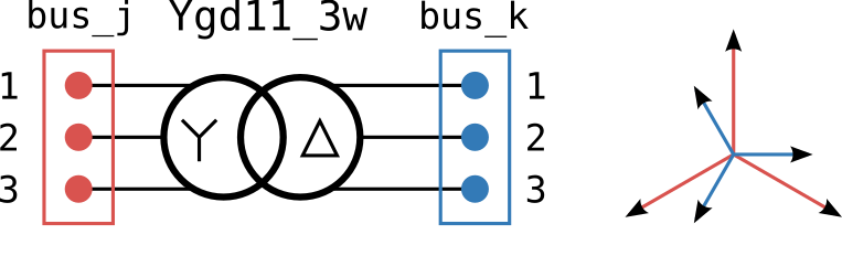
"transformers":[
            {"bus_j": "Bus_0",  "bus_k": "Bus_1",  "S_n_kVA": 2500.0, "U_j_kV":20, "U_k_kV":0.69,
             "R_cc_pu": 0.01, "X_cc_pu":0.04, "connection": "Ygd11_3w",   "conductors_j": 3, "conductors_k": 3},
                ],
where:
"bus_j": name of the j bus"bus_k": name of the k bus"pos_x": x position of the bus"pos_y": y position of the bus"S_n_kVA": based power in kVA"U_j_kV": HV side nominal RMS phase-phase voltage in kV"U_k_kV": LV side nominal RMS phase-phase voltage in kV"connection": connection type (see available connections)"conductors_j": HV side conductors"conductors_k": LV side conductors
| [T1] | Dugan, R. C., & Santoso, S. (2003). An example of 3-phase transformer modeling for distribution system analysis. 2003 IEEE PES Transmission and Distribution Conference and Exposition (IEEE Cat. No.03CH37495), 3, 1028–1032. https://doi.org/10.1109/TDC.2003.1335084 |